
The manufacturing industry demands increasingly lightweight and high-performance mechanical components, leading to a surge in the use of thin-walled plate-like structures. However, these designs present significant challenges during manufacturing. Casting and machining operations can introduce significant deformations due to factors such as residual stresses and improper clamping. This can result in dimensional inaccuracies, reduced fatigue life, and compromised performance. This article focuses on an automotive intermediate plate as a case study to explore effective strategies for minimizing deformation in thin-walled die-castings.
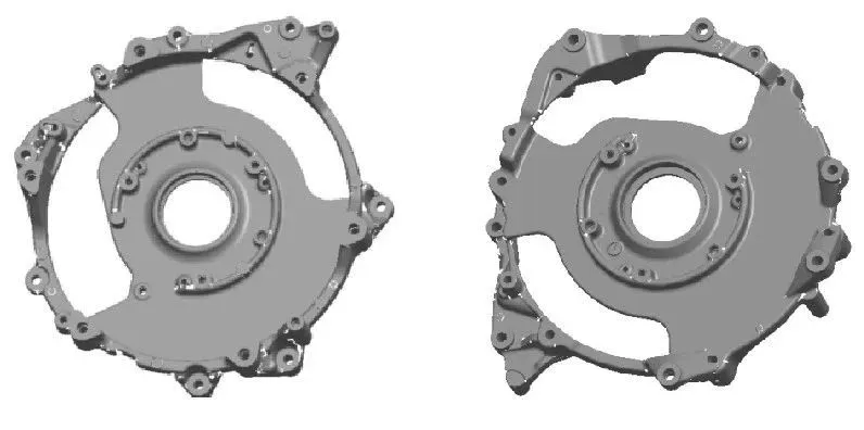
The middle plate is a key part used to fix the motors on both sides in a certain automobile gearbox. It weighs about 1.2kg and is made of ADC12 die-cast aluminum alloy. The appearance is shown in Figure 1. It is a typical thin-walled plate-like part, disc-shaped, with an outer size of about φ340mm. The wall thickness of the middle connection part is 5mm. In order to make the design lightweight, a large area is hollowed out, which greatly reduces the rigidity of the part and increases the difficulty of its die-casting and processing.

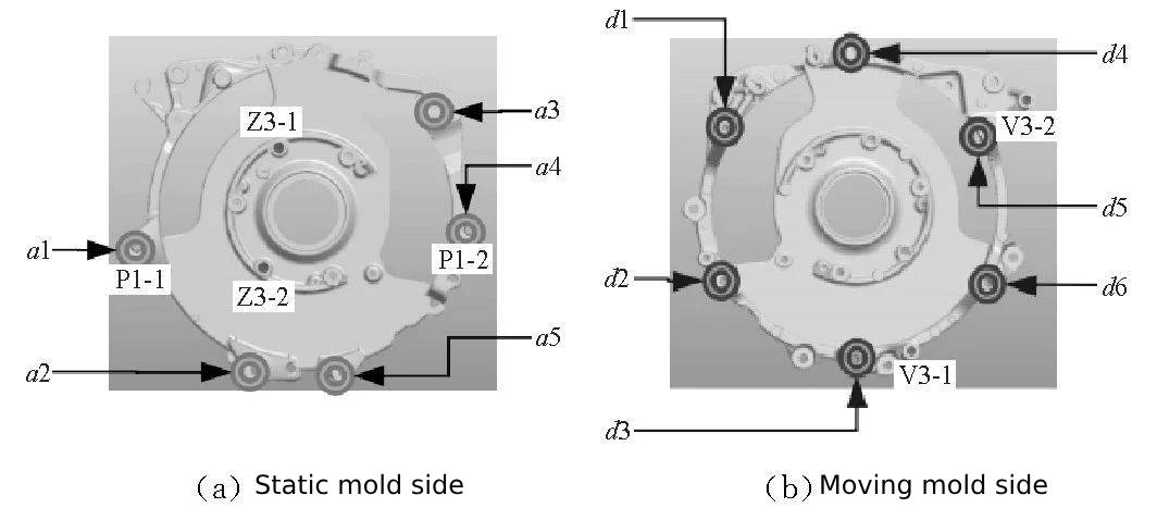

1.Press head 2. U-axis tailstock 3. Tailstock L plate 4. Fixture bottom plate 5. Diamond pin 6. Floating support 7. Fixed support 8. Pre-positioning guide column 9. Round pin
Due to the poor rigidity of the middle plate, a small clamping torque can also produce a lever effect, causing local deformation of the workpiece, rebound after processing, and reduce the processing accuracy. Therefore, the clamping point and support point of such parts must be set point to point, and the clamping force arm should be 0 as much as possible. The action sequence is: put the workpiece in place → clamp the fixed support → float the floating support → clamp the floating support clamping point.

Figure 4 Z3-2 hole Y-axis coordinate offset fluctuation diagram

Figure 5 X/Y-axis thermal offset of the vertical machining center
