
In the process of die-casting mold design, it is constantly demonstrated and coordinated with each other. When it comes to the mold structure, several schemes are often considered at the same time. The advantages and disadvantages of each structure are listed as far as possible for each structure, and each structure is analyzed and optimized. The specific steps of die casting mold design are as follows:
Step 1: Analysis and digestion of the 2D and 3D drawings of the product

Step 2: Determine the injection type
When selecting an injection, the designer mainly considers its plasticization rate, injection volume, clamping force, effective area of the installation mold (distance between the tie rods of the injection machine), modulus, ejection form, and fixed length.
Step 3: Determine the number of cavities and arrange the cavities
The number of mold cavities is mainly determined according to the projected area of the product, geometric shape (with or without side core pulling), product accuracy, batch size, and economic benefits.
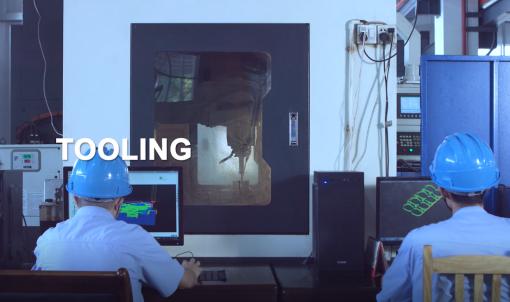
Step 4: Determine the parting surface
Generally speaking, the parting surface on the plane is easier to handle, and sometimes you should pay special attention to the parting surface of the three-dimensional form.
Step 5: Design of the gating system
The design of the gating system includes the selection of the main runner and the determination of the cross-sectional shape and size of the runner. When designing the gating system, the first step is to select the location of the gate. The proper selection of the gate location will directly affect the quality of the product molding and whether the injection process can proceed smoothly.
Step 6: Design of the ejector system
The ejection forms of products can be divided into three categories: mechanical ejection, hydraulic ejection, and pneumatic ejection. Mechanical ejection is the last link in the injection molding process. The quality of ejection will ultimately determine the quality of the product. Therefore, product ejection cannot be ignored.
Step 7: Design of the cooling system
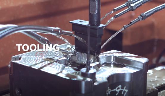
The design of the cooling system is a relatively tedious task, and the cooling effect, cooling uniformity, and the influence of the cooling system on the overall structure of the mold must be considered.
Step 8: The guide device on the die-casting injection mold has been determined when the standard mold base is used.
Under normal circumstances, designers only need to choose according to the specifications of the mold base. However, when precision guiding devices are required to be set according to product requirements, the designer must perform specific designs based on the mold structure.
Step 9: Selection of mold steel
The selection of materials for mold forming parts (cavity, core) is mainly determined according to the batch size of the casting and the material of the die casting.
Step 10: Draw an assembly drawing
After the ranking mold base and related content are determined, the assembly drawing can be drawn. In the process of drawing the assembly drawing, the selected pouring system, cooling system, core pulling system, ejection system, etc. have been further coordinated and improved to achieve a relatively perfect design in terms of structure.
Step 11: Drawing the main parts of the mold
When drawing a cavity or core diagram, it is necessary to pay attention to whether the given molding dimensions, tolerances, and demolding inclination are compatible, and whether the design basis is compatible with the design basis of the product. At the same time, the manufacturability of the cavity and core during processing and the mechanical properties and reliability during use must also be considered.
Step 12: The exhaust system plays a vital role in ensuring the quality of product molding. The exhaust methods are as follows:
1. Use the exhaust slot. The exhaust groove is generally located in the last part of the cavity to be filled. The depth of the vent groove varies with different plastics and is basically determined by the maximum clearance allowed when the plastic does not produce flash.
2. Use the matching clearance of cores, inserts, pushrods, etc., or special exhaust plugs for exhaust.
3. Sometimes in order to prevent vacuum deformation when the product is ejected, it is necessary to design a vent insert.
