
1. Product Introduction
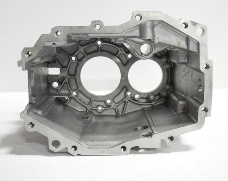
The following is a schematic diagram of the three-dimensional structure of a car transmission bracket. the wall thickness of the part is mostly 5 mm, the structure is relatively complex, and the mass of the billet is 855 g. The porosity of the die casting is in accordance with the standard VW50093, which requires no cracks, fractures, plastic deformation, etc. The alloy material is AlSi12Cu1Fe.

2. Die casting Process Design
2.1 Pouring System Design
The pouring row system can ensure the reasonable configuration of each area when the casting is filled, smooth exhaust, and reduce the involvement of gas as much as possible. The pouring system adopts multi-stage runner feeding, set in the long side position of the casting, in order to reduce the filling time of aluminum liquid, shorten the process of aluminum liquid, and avoid defects such as rolled gas, cold partition and fusion marks during die-casting.
2.2 Cooling System Design
Set cooling water in the wall thickness area of the casting to ensure the cooling effect of the wall thickness area, to avoid shrinkage and shrinkage holes in the wall thickness area. Cooling system design is affected by the ejector pin and core position, it is difficult to completely take care of all wall thickness areas of the casting, but still take care of the mold thermal balance and cooling of the wall thickness area of the casting as much as possible.
3. Process Optimization
The leftmost runner was widened by 5 mm to the left to make up for the lack of aluminum filling on the left side of the part; the slag collection bag in the central area was deepened to improve the slag discharge capacity; the rightmost runner was blocked and used as a slag collection bag to slow down the filling speed in the right side.

 NO.38 Duanzhou 3rd Road, Zhaoqing(526060), Guangdong, China